


Optimization of Rod Anode Tubes for X-ray Inspection of Aircraft Engine Welding
Thorsten FRÖBA*, Dr. Jens Peter STEFFEN*
*X-RAY WorX GmbH, Siemensstraße 26, D-30827Garbsen,Germany,www.x-ray-worx.com
Abstract. One of the major challenges for rod anode tubes used in microfocus X-ray inspection of aircraft engine parts is endurance. Industry standards like ASTM [1] require long exposure times of X-ray films at high X-ray intensity. To increase reliability and endurance of rod anode tubes new mechanical designs had to be developed and new cooling techniques needed to be applied.
This paper gives an overview over the general setup and application of microfocus rod anode tubes in industry with a special focus on aerospace industry. It discusses different technical challenges like heat reduction, improvement of the cooling process as well as the integration of sealings into the cooling circuit. It shows how the development team of X-RAY WorX solved the major issues to assemble a compact and durable rod anode tube for use in aircraft engine inspection. The new design of the rod anode tube decreases down times of the equipment and thus optimizes the process of X-ray inspection of the engine manufacturer.
1. Areas of Application
Radiography and radioscopy are common and widely accepted techniques for non-destructive testing. In a standard test setup an X-ray source is placed in front of the inspected part. An X-ray sensitive film or detector is placed behind the part to collect the remaining radiation that penetrated the part. In many setups the region of interest is found at positions that are inappropriate for this procedure.
Parts that have several cavities and high overall wall thickness may only be penetrated with insufficient results in terms of resolution or contrast. Examples are hollow chamber profiles [2] and heat exchangers [3], where several tubes are welded on a tube sheet. Inspecting the welds requires a narrow X-ray source that needs to be inserted into the tubes of the heat exchanger. Standard X-ray tubes have dimensions that do not allow this insertion
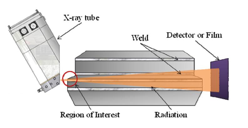
Figure 1: Weld Inspection using standard X-ray tube
Similar challenges can be found in inspection of aircraft engine parts. Here the X-ray source has to be moved very close to the weld. At the same time the film or detector needs to be positioned at the opposite side of the weld. With a standard X-ray tube it is not possible to move the source of X-ray close to the region of interest while avoiding the doubling of the penetrated wall thickness (compare figure 1). Effects of doubling the penetrated wall thickness are loss of contrast and resolution as well as overlap of details in the inspected regions
To meet the described challenges rod anode X-ray tubes were developed. The source of radiation is located at the top of a rod and can be inserted into cavities. Figure 2 illustrates the basic principle of using rod anode tubes to decrease the wall thickness that needs to be penetrated. Welding defects can of a rod and can be inserted into cavities. Figure 2 illustrates the basic principle of using rod anode tubes to decrease the wall thickness that needs to be penetrated. Welding defects can from the outside of the part.
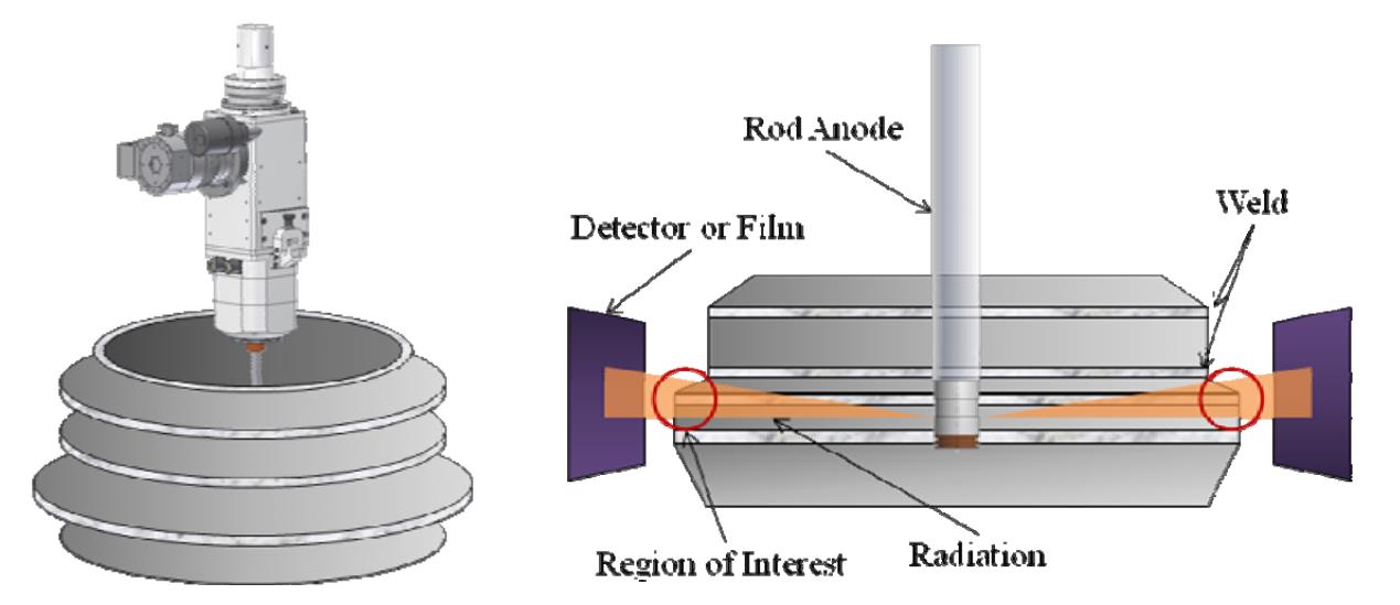
Figure 2: Weld Inspection using Rod Anode
Increasing requirements for quality and security are leading to lower tolerance levels for various weld defects. In electron beam welding missed joints may have depths of less than 50µm [4]. This also has an impact on the X-ray sources used for inspection. The major \impact is the need for smaller X-ray focal spot sizes. The focal spot size is the diameter of the area inside the X-ray source that emits radiation. Microfocus X-ray tubes are the solution when high magnification and high resolution of the resulting X-ray image are key requirements.
2. Microfocus Rod Anode Tubes
Microfocus rod anode tubes combine the advantages of microfocus X-ray tubes and a rod anode tubes. Figure 3 shows a modern microfocus rod anode tube. It produces a very small X-ray focal spot that can be positioned in cavities very close to very close to the area of interest.
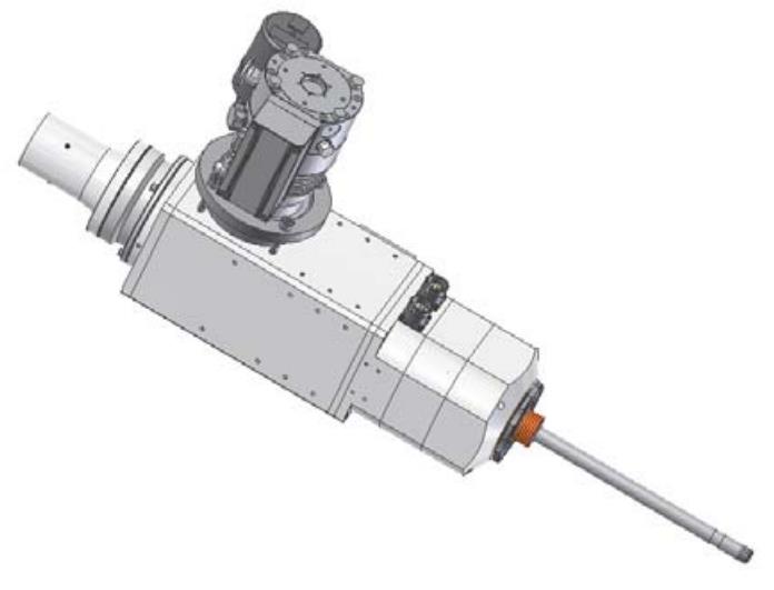
Figure 3: Microfocus Rod Anode Tube
The X-ray focal spot of a rod anode tube is generated at the target, compare figure 5. The target is located in the head of the rod anode. Depending on the shape of the target different beam characteristics can be generated. Basically four different types of beam characteristics can be distinguished as described in table 1.
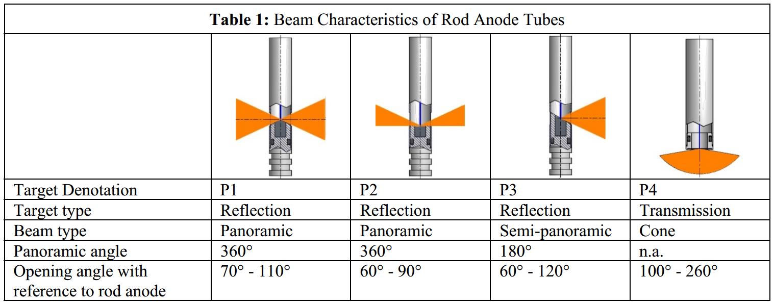
Panoramic targets are mainly used in pipe construction and aircraft engine inspection. Reflection targets are needed to control tube sheet welds whereas transmission targets have their main application in tank inspection.
3. Challenges in Microfocus Radiography with Rod Anode Tubes
Optimizing production processes means saving time while concurrently keeping the quality high. Decreasing inspection times when inspecting welds basically means decreasing exposure time of X-ray sensitive films or detectors. This can be achieved by delivering higher X-ray intensity while keeping the focal spot at a constant size.
To increase X-ray intensity an X-ray tube needs to be operated at higher current. Higher current introduces a higher amount of heat into the rod anode and the target. This line of 3reasoning leads to the core problem of microfocus X-ray technology, namely the deduction of heat from the target and sealings.
Heat leads to degradation of the Tungsten target layer as well as degradation of the O-ring sealings that keep the vacuum stable inside the tube. Thus in microfocus X-ray technology heat is the classical antagonist of stability and endurance.
Standard microfocus rod anode tubes have a target cooling where the cooling agent is lead in at the head of the rod anode. This makes handling of the rod anode inconvenient. The cooling of the target and O-ring sealings is insufficient because the cooling agent is passing on the back side of the target (compare figure 4). This may lead to unstable vacuum during continuous operation.
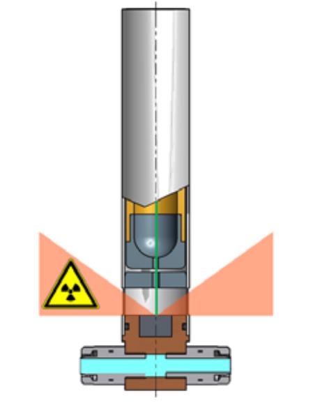
Figure 4: Standard Microfocus Rod Anode with external cooling
4. Improvement of Performance by Internal Cooling
The new developed microfocus rod anode tubes have a different type of cooling. Internal cooling channels lead the cooling agent through the rod towards the head. The cooling agent is directly cooling the O-ring sealings and target (see figure 5). This allows easier handling and positioning of the rod anode and generates stable vacuum conditions.
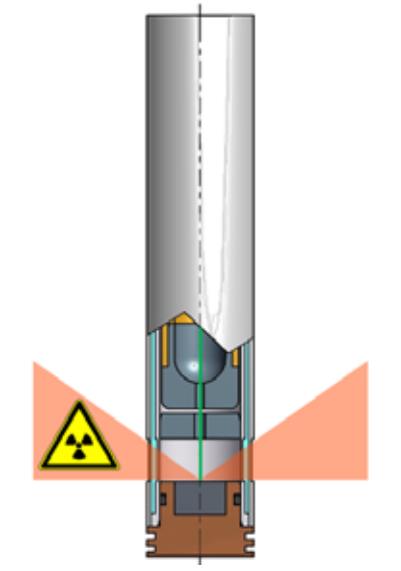
Figure 5: Optimized Rod Anode with internal Cooling
The advanced design of the cooling allows the e tube power to be increased up to 100W. This increases X-ray intensity and shortens inspection time. Furthermore the improved cooling significantly improves the endurance of the O-ring sealings which leads to lower maintenance effort and higher overall endurance of the complete rod anode tube.
An example for the improvement of handling is shown in figure 6. By cooling internally the diameter of the rod is reduced. Smaller cavities become accessible.
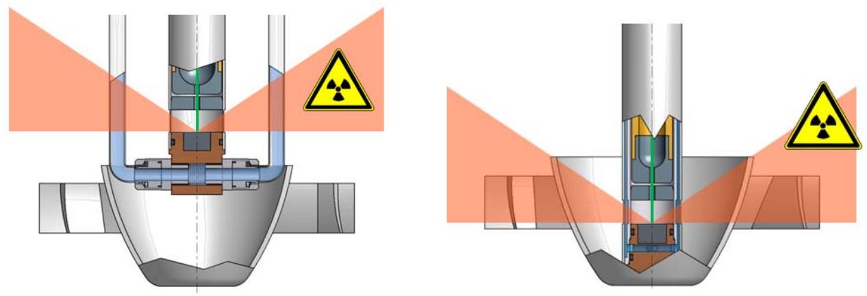
Figure 6: Advantages of improved design of the rod anode
References
[1] ASTM E1032 - 06 Standard Test Method for Radiographic Examination of Weldments
[2] Schröder, G., Pauly, F., Untersuchung von Verbindung und Struktur geschweißter Aluminium-
Strangpressprofile, Berichte des Forschungszentrum Jülich, 3944, S.11 ff
(http://juwel.fz-juelich.de:8080/dspace/bitstream/2128/2590/1/Juel_3944_Schroeder.pdf )
[3] Ding, K., Chen, G., Shou, B., Zhang, X., Huang, D., Digital Radiographic Imaging Inspection System on
The Tube to Tube Sheet Welding Joints of Heat Exchanger, Proceedings of the WCNDT 2008, Shanghai.
(http://www.ndt.net/article/wcndt2008/papers/31.pdf )
[4] Kumar, A. and Kumar, S.,
X-Ray Radiography of EB Welded Joints inIndia, Proceedings of the National
Seminar on Non-Destructive Evaluation, 2006,Hyderabad
(http://www.ndt.net/article/nde-india2006/files/tp-49-pap.pdf )